The Channels of Optical Transceiver
2024-04-19
Optical transceivers play a pivotal role in modern telecommunications and networking by enabling the transmission and reception of optical signals over fiber optic cables. These devices utilize various channels to facilitate the transfer of data, monitor performance, and ensure compatibility within network infrastructures. Understanding the channels of an optical transceiver is essential for optimizing network performance, troubleshooting issues, and maintaining reliable communication. Let's delve into the intricate workings of these channels:
1. Transmission Channel:
The transmission channel is responsible for converting electrical signals into optical signals for transmission over fiber optic cables. This channel comprises several key components:
- Electrical Interface: At the input side of the transceiver, electrical signals from network equipment such as routers or switches are received through interfaces such as SFP, SFP+, QSFP, or QSFP28.
- Laser Driver: The electrical signals are amplified and modulated by the laser driver to drive the laser diode or semiconductor optical amplifier (SOA).
- Laser Diode or SOA: The laser diode or SOA emits optical signals at specific wavelengths corresponding to the desired transmission medium, such as single-mode or multi-mode fiber.
- Optical Multiplexer: In some transceivers, an optical multiplexer combines multiple optical signals onto a single fiber for transmission, optimizing bandwidth utilization.
The transmission channel is responsible for converting electrical signals into optical signals for transmission over fiber optic cables. This channel comprises several key components:
- Electrical Interface: At the input side of the transceiver, electrical signals from network equipment such as routers or switches are received through interfaces such as SFP, SFP+, QSFP, or QSFP28.
- Laser Driver: The electrical signals are amplified and modulated by the laser driver to drive the laser diode or semiconductor optical amplifier (SOA).
- Laser Diode or SOA: The laser diode or SOA emits optical signals at specific wavelengths corresponding to the desired transmission medium, such as single-mode or multi-mode fiber.
- Optical Multiplexer: In some transceivers, an optical multiplexer combines multiple optical signals onto a single fiber for transmission, optimizing bandwidth utilization.
2. Reception Channel:
The reception channel of an optical transceiver is responsible for converting incoming optical signals back into electrical signals for processing by network equipment. It comprises the following components:
- Photodetector: Incoming optical signals are received by a photodetector such as a photodiode or avalanche photodiode, which converts them into electrical signals.
- Transimpedance Amplifier (TIA): The electrical signals from the photodetector are amplified and converted into voltage signals by the TIA, enhancing their readability and reducing noise.
- Signal Conditioning Circuitry: Additional circuitry may be included to condition and preprocess the received signals before transmitting them to the output interface.
- Output Interface: The processed electrical signals are transmitted to the output interface of the transceiver, where they are connected to network equipment for further processing and routing.
The reception channel of an optical transceiver is responsible for converting incoming optical signals back into electrical signals for processing by network equipment. It comprises the following components:
- Photodetector: Incoming optical signals are received by a photodetector such as a photodiode or avalanche photodiode, which converts them into electrical signals.
- Transimpedance Amplifier (TIA): The electrical signals from the photodetector are amplified and converted into voltage signals by the TIA, enhancing their readability and reducing noise.
- Signal Conditioning Circuitry: Additional circuitry may be included to condition and preprocess the received signals before transmitting them to the output interface.
- Output Interface: The processed electrical signals are transmitted to the output interface of the transceiver, where they are connected to network equipment for further processing and routing.
3. Control and Monitoring Channels:
Optical transceivers often include control and monitoring channels to facilitate communication with network equipment and provide real-time performance monitoring. These channels include:
- Serial Interface: A serial interface, such as I2C (Inter-Integrated Circuit) or SPI (Serial Peripheral Interface), is commonly used for communication between the transceiver and the host device (e.g., router or switch).
- Digital Diagnostics Monitoring (DDM): DDM allows for real-time monitoring of key parameters such as optical power levels, temperature, voltage, and laser bias current, enabling proactive maintenance and troubleshooting.
- Alarm and Status Indicators: LEDs or other indicators provide visual feedback on the operational status of the transceiver, indicating normal operation, fault conditions, or link activity.
- Configuration and Control Registers: These registers allow for the configuration of various parameters and settings of the transceiver, such as wavelength, modulation format, and transmission power.
Optical transceivers often include control and monitoring channels to facilitate communication with network equipment and provide real-time performance monitoring. These channels include:
- Serial Interface: A serial interface, such as I2C (Inter-Integrated Circuit) or SPI (Serial Peripheral Interface), is commonly used for communication between the transceiver and the host device (e.g., router or switch).
- Digital Diagnostics Monitoring (DDM): DDM allows for real-time monitoring of key parameters such as optical power levels, temperature, voltage, and laser bias current, enabling proactive maintenance and troubleshooting.
- Alarm and Status Indicators: LEDs or other indicators provide visual feedback on the operational status of the transceiver, indicating normal operation, fault conditions, or link activity.
- Configuration and Control Registers: These registers allow for the configuration of various parameters and settings of the transceiver, such as wavelength, modulation format, and transmission power.
4. Auxiliary Channels:
Some optical transceivers may feature auxiliary channels for specialized functions or applications, such as:
- Clock and Timing Channels: In applications requiring precise synchronization, dedicated clock and timing channels may be utilized to ensure accurate signal timing and alignment.
- Management and Provisioning Channels: These channels enable remote management and provisioning of the transceiver, allowing for configuration changes, firmware updates, and performance monitoring from a centralized management system.
- Redundancy and Failover Channels: In mission-critical applications, redundant channels may be employed to provide automatic failover and redundancy, ensuring uninterrupted operation in the event of a component failure or link degradation.
Some optical transceivers may feature auxiliary channels for specialized functions or applications, such as:
- Clock and Timing Channels: In applications requiring precise synchronization, dedicated clock and timing channels may be utilized to ensure accurate signal timing and alignment.
- Management and Provisioning Channels: These channels enable remote management and provisioning of the transceiver, allowing for configuration changes, firmware updates, and performance monitoring from a centralized management system.
- Redundancy and Failover Channels: In mission-critical applications, redundant channels may be employed to provide automatic failover and redundancy, ensuring uninterrupted operation in the event of a component failure or link degradation.
5. Wavelength Channels:
Wavelength channels refer to the specific wavelengths of light used for transmission and reception within the optical transceiver. Different wavelengths are utilized for different types of fiber optic cables and transmission media:
- Single Wavelength: Some transceivers operate at a single fixed wavelength, typically in the infrared range, optimized for specific fiber types and transmission distances.
- Wavelength Division Multiplexing (WDM): Advanced transceivers may utilize WDM technology to transmit and receive multiple optical signals simultaneously over a single fiber, each at a different wavelength. This allows for increased bandwidth capacity and efficient utilization of fiber infrastructure.
Wavelength channels refer to the specific wavelengths of light used for transmission and reception within the optical transceiver. Different wavelengths are utilized for different types of fiber optic cables and transmission media:
- Single Wavelength: Some transceivers operate at a single fixed wavelength, typically in the infrared range, optimized for specific fiber types and transmission distances.
- Wavelength Division Multiplexing (WDM): Advanced transceivers may utilize WDM technology to transmit and receive multiple optical signals simultaneously over a single fiber, each at a different wavelength. This allows for increased bandwidth capacity and efficient utilization of fiber infrastructure.
In summary, the channels of an optical transceiver encompass various functional aspects, including transmission, reception, control, monitoring, and auxiliary functions. Understanding these channels is essential for deploying, configuring, and maintaining optical transceivers within telecommunications and networking environments, ensuring reliable and efficient communication over fiber optic networks.
MPO Connector Inspection Solution(1)
What are the Types of Huawei Switches?
Artículo relacionado
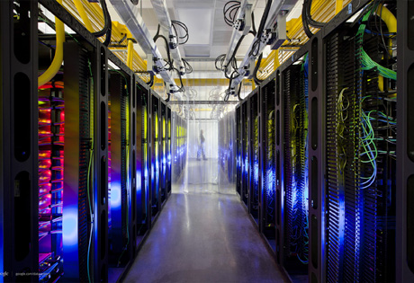
By the end of 2024, there will be 5,697 public data centers worldwide, including 5,186 colocation sites and 511 hyperscale sites.
Global Data Center Status and Trends

By the end of 2024, there will be 5,186 colocation data centers worldwide. With a compound annual growth rate (CAGR) of 6.6%, the number of colocation data centers will increase to 7,640 by 2030.
Where are The World's Data Centers?