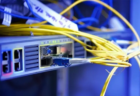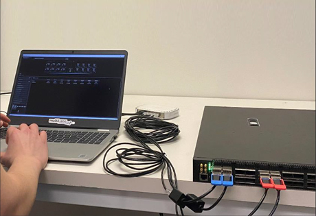
MPO Connector Inspection Solution(1)
2024-04-26
With the acceleration of digital transformation and the widespread application of new technologies, the demand for IP traffic and bandwidth in global data centers has shown explosive growth, bringing unprecedented opportunities and challenges to the industry. Driven by new technologies such as cloud computing, big data analysis and artificial intelligence, enterprises' demand for data storage and processing capabilities continues to rise.
However, the sharp increase in network bandwidth demand has put network facilities under tremendous pressure. Data center managers need to continuously upgrade and optimize network equipment, including increasing port density and supporting higher channel speeds (such as 200G, 400G or even higher). , and achieve lower latency. In addition, IT network administrators and operators need to pay close attention to customer needs, because customers have a very low tolerance for network downtime. According to the Pangman Institute, the cost of data center downtime continues to rise, further exacerbating the importance of network stability and reliability.
To address these challenges, multi-fiber push-on (MPO) connectors have become the preferred solution for data center infrastructure due to their unique advantages. However, we also need to be aware of the potential network failure risks of MPO connectors and handle them with caution.
Why use MPO connections?
To date, MPO connectors are the only connector solution capable of supporting all TIA and IEEE standards from 40G to 400G while also meeting the critical need for high fiber density in data centers. Other benefits of MPO connectivity include:
① Supports duplex LC-MPO and parallel optical MPO-MPO applications.
② It is scalable and can provide services for all emerging high-speed networks.
③ Compatible with a variety of optical fiber geometries (such as SMF, OM2, OM3, OM4 and OM5) and wavelength division multiplexing (WDM) technology.
④ Optimize the space layout of patch panels and racks to prevent crowding and improve air circulation and cooling efficiency.
⑤ Reduce the time and labor costs associated with single-fiber installations and moves, adds, and changes (MACs).
① Supports duplex LC-MPO and parallel optical MPO-MPO applications.
② It is scalable and can provide services for all emerging high-speed networks.
③ Compatible with a variety of optical fiber geometries (such as SMF, OM2, OM3, OM4 and OM5) and wavelength division multiplexing (WDM) technology.
④ Optimize the space layout of patch panels and racks to prevent crowding and improve air circulation and cooling efficiency.
⑤ Reduce the time and labor costs associated with single-fiber installations and moves, adds, and changes (MACs).
In practical applications, multimode fiber often replaces single-mode fiber when the interconnection distance is 150 meters (about 500 feet) or less, especially in patch panels and racks where a large number of ports and thousands of fibers need to be placed Area of links and connectors. In colocation facilities and multi-tenant buildings, MPO trunks and cross-connects are also commonly used in the two guest rooms at the far end of the facility. These areas serve as hubs for the data center to connect to multiple telecom carriers/service providers and then directly Connecting to client suite.
Today's evolving data centers require solutions that are fast, easy and efficient. Before EXFO introduced its new (scan knob-less) automated multi-fiber connector inspection solution, MPO inspection relied primarily on manual operations, which were cumbersome, time-consuming, error-prone, or often not inspected at all. By exploring the causes of MPO connections, the causes of potential connector failures, and the versatile nature of this multi-fiber inspection tool, network administrators can ensure their data center connectivity infrastructure is operating properly and achieve zero-downtime performance.
Problems with traditional multi-fiber detection
Ironically, although MPO connectors can install up to 12, 24 or even 32 optical fibers in the same space as a single fiber connector, this ability also brings a lot of trouble. There is widespread industry agreement that connector contamination and damage are the leading causes of fiber optic network failures, as evidenced by the renowned NTT Advanced Technology study in the chart below. Tiny dust, dirt, particles, and even fingertip oil inadvertently left during the operation of the connector may contaminate the connector, thereby seriously damaging the connector end face and optical fiber, and hindering its normal mating. This poor physical connection not only results in high bit error rates, but also potential packet loss and latency, ultimately causing severe downtime and network failure.

Top causes of fiber optic network outages and failures (Source: NTT Advanced Technology Study)
Basically, the most popular MPO connectors can be divided into two fiber row MT ferrule configurations:
① 12-fiber row (1x12 with a total of 12 fibers and 2x12 with a total of 24 fibers)
② 16-core row (1x16 with a total of 16 fibers and 2x16 with a total of 32 fibers); 32-core MPO supports IEEE’s current 400G standard.
In these MPO connector configurations, the chance of experiencing a connector failure is 12 to 32 times greater, significantly increasing the risk of severe downtime or network failure.
To ensure stable performance of multi-fiber connectors, a complete inspection of all connector end faces and every fiber in the array, including unused fibers, must be performed. As shown in the figure, the distance between optical fibers in an MPO connector is only a few microns, which requires inspection accuracy to reach the micron level. Unfortunately, traditional inspection tools, which scan connectors with a knob, often fail to achieve this standard of accuracy, leaving technicians and installers frustrated with the time-consuming and already error-prone process of manually scanning each fiber. And in many data centers' already overcrowded panels, technicians often struggle to find enough space to operate the scan knobs.

12-core and 24-core MPO connectors, the spacing between fibers is very tight
In practice, EXFO has found that technicians and installers often skip the time-consuming, cumbersome and unreliable traditional MPO inspection process and go directly to link loss testing, assuming that as long as the insertion loss results are good and within the loss budget, there is no need to examine.
However, this simplified approach comes with certain risks. Due to the relatively limited link loss budget and the "push on" functionality of MPO connectors, they are more sensitive to unwanted reflections. Especially at rates above 10G, MPO connectors are more prone to failure. In the single-mode fiber example shown below, oil contamination on the technician's fingers while handling the connector caused a significant change in return loss (from 10dB to 12dB at 10G). While oil contamination does not create air gaps at 10G and therefore does not affect insertion loss, at 25G rates this increase in return loss is enough to cause serious network failures as it significantly reduces bit error rate testing ( BERT) performance.

Return loss of clean and oily connectors (average difference in return loss is 10dB-12dB)
Notably, proper inspection of MPO connectors produces clear images of the connector endface and all optical fibers, allowing technicians to accurately identify issues that may be missed with traditional insertion loss testing, whether they be dirt or damage.
Some technicians have made a habit of systematically cleaning each connector without inspecting it first, even though the connector may not need cleaning. By doing an inspection first, you can save thousands of dollars on cleaning supplies. For example, at $0.50 per cleaner click, a system cleaning 10,000 connectors would incur up to $5,000 in additional costs. Additionally, different contaminants may require the use of specific cleaning methods such as solvents. Importantly, however, a damaged connector cannot be repaired by cleaning, which only ensures that the surface is clean, not that it functions properly. Inspection is a critical step in ensuring good connector quality.
Best practice procedures for MPO and all connectors are as follows:
① First, perform an inspection to identify the presence of contamination or damage.
② If dirt or contaminants are found, the connector should be thoroughly cleaned using the manufacturer's cleaning products and procedures.
③ Check again and repeat the above process until the connector (including all optical fibers and end faces) is completely clean.
④ Restore link loss testing or other tests based on your specific application.
① First, perform an inspection to identify the presence of contamination or damage.
② If dirt or contaminants are found, the connector should be thoroughly cleaned using the manufacturer's cleaning products and procedures.
③ Check again and repeat the above process until the connector (including all optical fibers and end faces) is completely clean.
④ Restore link loss testing or other tests based on your specific application.
MPO Connector Inspection Solution(2)
The Channels of Optical Transceiver
Artículo relacionado

By the end of 2024, there will be 5,697 public data centers worldwide, including 5,186 colocation sites and 511 hyperscale sites.
Global Data Center Status and Trends

By the end of 2024, there will be 5,186 colocation data centers worldwide. With a compound annual growth rate (CAGR) of 6.6%, the number of colocation data centers will increase to 7,640 by 2030.
Where are The World's Data Centers?