The Transmission Distance of Optical Transceivers
2024-06-07
Optical transceivers are critical components in fiber optic communication networks, serving as the interface between the electrical signals used by networking equipment and the optical signals transmitted over fiber optic cables. The transmission distance of optical transceivers is a key performance parameter, influenced by several factors including the type of fiber optic cable, the wavelength of light used, and the transceiver's design and technology. Here’s a detailed exploration of the factors affecting the transmission distance of optical transceivers:
1. Type of Fiber Optic Cable
The two primary types of fiber optic cables are single-mode fiber (SMF) and multi-mode fiber (MMF). Each has distinct characteristics that impact transmission distance.
Single-Mode Fiber (SMF):
- Core Diameter: SMF has a small core diameter, typically around 9 micrometers, allowing it to transmit light with minimal dispersion over long distances.
- Transmission Distance: SMF is ideal for long-distance communication, often supporting distances up to 80-100 km or more without requiring signal regeneration. With advanced technologies and equipment, distances can extend even further.
- Use Cases: SMF is used in long-haul telecommunications, metropolitan area networks (MANs), and high-speed data centers.
- Core Diameter: SMF has a small core diameter, typically around 9 micrometers, allowing it to transmit light with minimal dispersion over long distances.
- Transmission Distance: SMF is ideal for long-distance communication, often supporting distances up to 80-100 km or more without requiring signal regeneration. With advanced technologies and equipment, distances can extend even further.
- Use Cases: SMF is used in long-haul telecommunications, metropolitan area networks (MANs), and high-speed data centers.
Multi-Mode Fiber (MMF):
- Core Diameter: MMF has a larger core diameter, typically 50 or 62.5 micrometers, which supports multiple modes or light paths.
- Transmission Distance: MMF is suited for shorter distances due to higher modal dispersion. Typical distances range from 300 meters to 2 km, depending on the transceiver type and network requirements.
- Use Cases: MMF is commonly used in local area networks (LANs), data centers, and intra-building applications.
- Core Diameter: MMF has a larger core diameter, typically 50 or 62.5 micrometers, which supports multiple modes or light paths.
- Transmission Distance: MMF is suited for shorter distances due to higher modal dispersion. Typical distances range from 300 meters to 2 km, depending on the transceiver type and network requirements.
- Use Cases: MMF is commonly used in local area networks (LANs), data centers, and intra-building applications.
2. Wavelength of Light
Optical transceivers operate at various wavelengths, primarily in the infrared range. The choice of wavelength affects the transmission distance due to different levels of attenuation and dispersion.
Common Wavelengths:
- 850 nm: Used primarily with MMF. Suitable for short-range applications, typically up to 300-400 meters.
- 1310 nm: Commonly used for intermediate distances on both SMF and MMF. For SMF, it can support distances up to 10-40 km.
- 1550 nm: Ideal for long-distance transmission on SMF due to lower attenuation. It can support distances up to 80-100 km, and with additional technologies like erbium-doped fiber amplifiers (EDFAs), even longer distances can be achieved.
- 850 nm: Used primarily with MMF. Suitable for short-range applications, typically up to 300-400 meters.
- 1310 nm: Commonly used for intermediate distances on both SMF and MMF. For SMF, it can support distances up to 10-40 km.
- 1550 nm: Ideal for long-distance transmission on SMF due to lower attenuation. It can support distances up to 80-100 km, and with additional technologies like erbium-doped fiber amplifiers (EDFAs), even longer distances can be achieved.
3. Transceiver Technology and Design
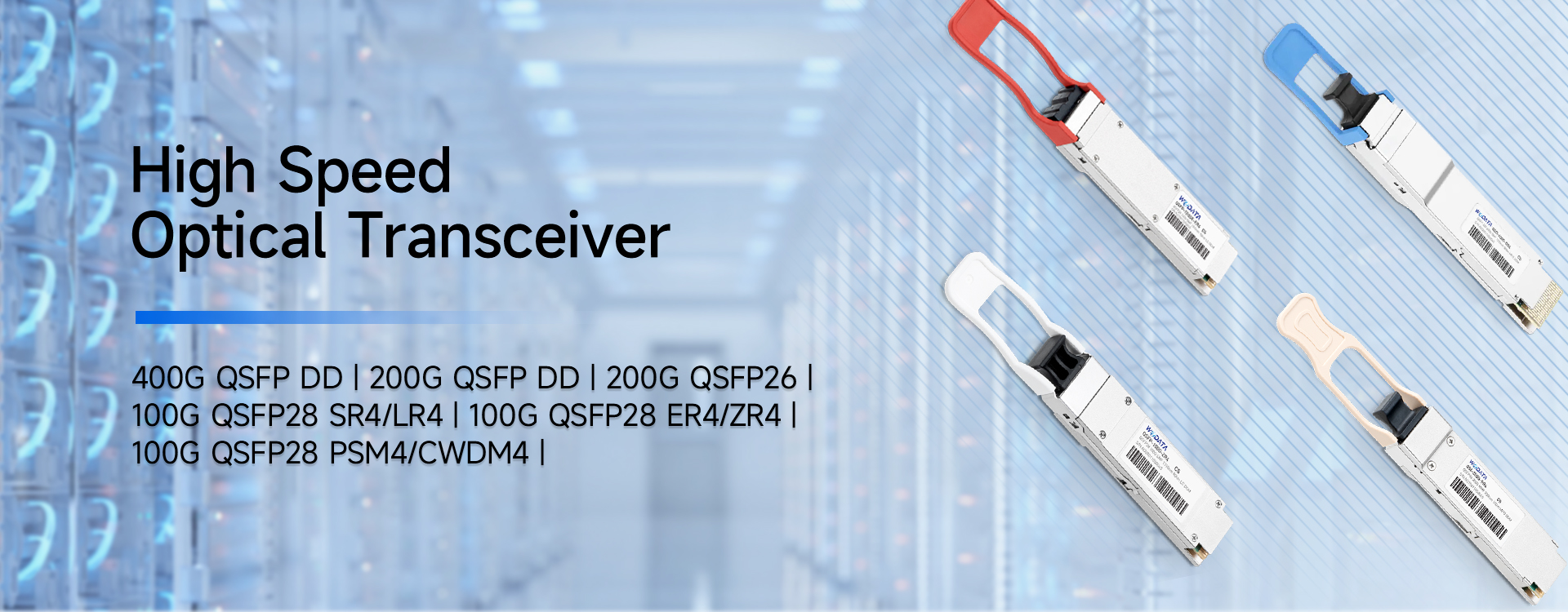
Different types of optical transceivers, such as SFP (Small Form-Factor Pluggable), SFP+, QSFP (Quad Small Form-Factor Pluggable), and QSFP28, have varying capabilities that influence transmission distance.
Types of Transceivers:
- SFP/SFP+: Typically used for Gigabit Ethernet (1 Gbps) and 10 Gigabit Ethernet (10 Gbps). SFP+ can support distances up to 40 km on SMF with the right optics.
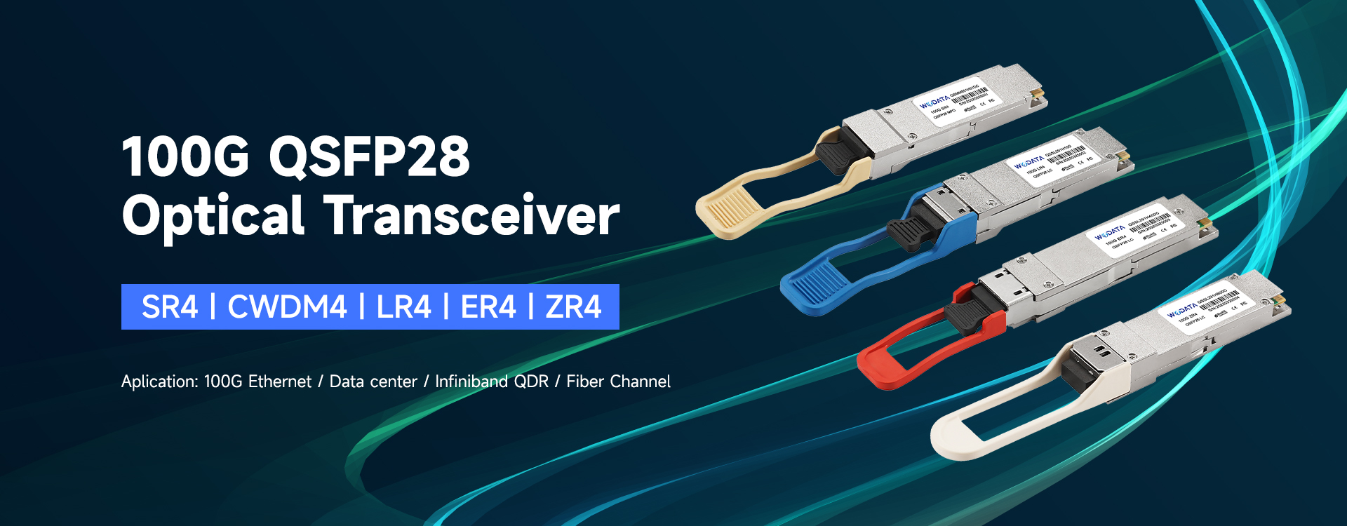
- QSFP/QSFP28: Used for 40 Gigabit Ethernet (40 Gbps) and 100 Gigabit Ethernet (100 Gbps). QSFP28, for example, can support up to 10 km on SMF for 100 Gbps applications.
- SFP/SFP+: Typically used for Gigabit Ethernet (1 Gbps) and 10 Gigabit Ethernet (10 Gbps). SFP+ can support distances up to 40 km on SMF with the right optics.
- QSFP/QSFP28: Used for 40 Gigabit Ethernet (40 Gbps) and 100 Gigabit Ethernet (100 Gbps). QSFP28, for example, can support up to 10 km on SMF for 100 Gbps applications.
Design Features:
- Optical Power Budget: The difference between the transmitted optical power and the receiver sensitivity. A higher power budget allows for longer transmission distances.
- Modulation Techniques: Advanced modulation techniques such as Dense Wavelength Division Multiplexing (DWDM) and Coherent Optical Technology enhance transmission distance by allowing more efficient use of the fiber’s bandwidth and improving signal integrity over long distances.
- Optical Power Budget: The difference between the transmitted optical power and the receiver sensitivity. A higher power budget allows for longer transmission distances.
- Modulation Techniques: Advanced modulation techniques such as Dense Wavelength Division Multiplexing (DWDM) and Coherent Optical Technology enhance transmission distance by allowing more efficient use of the fiber’s bandwidth and improving signal integrity over long distances.
4. Dispersion and Attenuation
Dispersion:
- Modal Dispersion: Primarily affects MMF. It occurs when different modes of light travel at different speeds, leading to signal spreading and distortion over distance.
- Chromatic Dispersion: Affects both SMF and MMF. It occurs when different wavelengths of light travel at different speeds. This can be mitigated using dispersion-shifted fibers and dispersion compensation techniques.
- Modal Dispersion: Primarily affects MMF. It occurs when different modes of light travel at different speeds, leading to signal spreading and distortion over distance.
- Chromatic Dispersion: Affects both SMF and MMF. It occurs when different wavelengths of light travel at different speeds. This can be mitigated using dispersion-shifted fibers and dispersion compensation techniques.
Attenuation:
- Intrinsic Attenuation: Caused by the absorption and scattering of light within the fiber. It is generally lower in SMF, especially at the 1550 nm wavelength.
- Extrinsic Attenuation: Caused by external factors such as bending losses, connector losses, and splicing losses. Proper installation and maintenance practices can minimize these losses.
- Intrinsic Attenuation: Caused by the absorption and scattering of light within the fiber. It is generally lower in SMF, especially at the 1550 nm wavelength.
- Extrinsic Attenuation: Caused by external factors such as bending losses, connector losses, and splicing losses. Proper installation and maintenance practices can minimize these losses.
5. Regeneration and Amplification
For very long distances, beyond the intrinsic capabilities of optical transceivers and fibers, signal regeneration and amplification become necessary.
Regeneration:
- Optical-Electrical-Optical (OEO) Conversion: Involves converting the optical signal to an electrical signal, amplifying and regenerating it, and then converting it back to an optical signal. This method is typically used in very long-haul networks.
- Optical-Electrical-Optical (OEO) Conversion: Involves converting the optical signal to an electrical signal, amplifying and regenerating it, and then converting it back to an optical signal. This method is typically used in very long-haul networks.
Amplification:
- Erbium-Doped Fiber Amplifiers (EDFAs): Used to amplify the optical signal directly without conversion to electrical form. EDFAs are effective at the 1550 nm wavelength, extending transmission distances significantly.
- Erbium-Doped Fiber Amplifiers (EDFAs): Used to amplify the optical signal directly without conversion to electrical form. EDFAs are effective at the 1550 nm wavelength, extending transmission distances significantly.
6. Environmental Factors
Environmental conditions such as temperature variations and physical stress on the fiber can impact transmission performance. Proper environmental controls and fiber management practices help maintain optimal transmission distances.
Temperature Control: Maintaining stable operating temperatures for transceivers and fiber can prevent signal degradation due to temperature-induced variations.
Physical Protection: Ensuring fibers are properly installed and protected from physical damage helps maintain signal integrity and prevents attenuation increases.
Conclusion
The transmission distance of optical transceivers is a complex interplay of fiber type, wavelength, transceiver technology, dispersion, attenuation, and external factors. Single-mode fibers, typically operating at 1310 nm or 1550 nm, are suited for long-distance transmission, often exceeding 80 km. Multi-mode fibers, operating primarily at 850 nm, are better suited for shorter distances, typically within a few hundred meters.
Advanced transceiver designs, including those using DWDM and coherent technology, extend the capabilities of optical networks, allowing for high-bandwidth communication over vast distances. Additionally, the use of amplification and regeneration technologies further enhances the transmission range, enabling robust and extensive fiber optic networks.
Understanding these factors and their interactions is essential for designing and deploying effective fiber optic communication systems, ensuring high performance and reliability over the desired transmission distances.
MTP/MPO Trunk Fiber Patch Cord
List the Optical Transceiver Wavelengths
Related Article
By the end of 2024, there will be 5,697 public data centers worldwide, including 5,186 colocation sites and 511 hyperscale sites.
Global Data Center Status and Trends

By the end of 2024, there will be 5,186 colocation data centers worldwide. With a compound annual growth rate (CAGR) of 6.6%, the number of colocation data centers will increase to 7,640 by 2030.
Where are The World's Data Centers?