Methods to Determine Abnormalities in Optical Modules
2023-11-23
Network workers often encounter various optical module problems. So if we encounter a fault, how should we conduct troubleshooting and analysis? In this article, we will talk about several common methods for judging optical module abnormalities.
Check whether the optical module model matches
Check whether the optical module type and the peer end match according to the Transceiver Type item. For example, if the opposite end uses a GE optical module and the local end uses a 10GE optical module, the interface will not go Up. You can replace the optical module on the local end or the opposite end according to the actual situation to make the optical module speeds on both ends consistent.
Check the transmission distance of the optical module according to the Transfer Distance item, and determine whether its length is within the transmission distance range supported by the optical module based on the type of optical fiber currently used. For example: OM3 type optical fiber supports a transmission distance of 150 meters. If the actual transmission distance exceeds 150 meters, a higher-level optical fiber needs to be replaced.
If there is a LOS Alarm alarm in Alarm information, it means that no signal is sent from the opposite end. It is suspected that the peer end or the optical module is abnormal.
Check whether the receiving and receiving light power is normal
If the receiving power is low, it means that the signal sent by the opposite end is not good, and the port may not be Up or the packets sent and received may be discarded after Up. In this case, please first check whether the transmission distance is too far and whether it exceeds the transmission distance of the optical module. Then check whether the optical module and optical fiber are damaged.
If the received power is high, it means that the signal at the opposite end is too strong. The possible reason is that the optical module is a long-distance optical module and the actual transmission distance is too short, causing the signal to not attenuate. At this time, the optical attenuation should be added to the optical module to prevent the light from being attenuated. module for protection.
If the sending power is low, it means that the optical module is not sending a good signal, which may cause the receiving power of the opposite end to be low, causing the port not to go Up or causing messages to be sent and received to be discarded after going Up.
If the transmit power is high, it means that the signal sent by the optical module is too strong, which may cause the opposite end to receive a high power, causing the opposite end optical module to burn out due to the continued high received power.
Self-loop test whether the optical module is normal
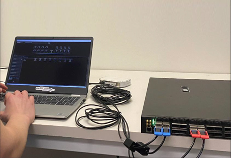
Use an optical fiber to connect the TX side and RX side of the optical module, and perform a self-loop test on the optical module (long-distance optical modules must be interconnected through optical attenuation devices). If the interface indicator light is always on, the interface can be Up, indicating that this The interface and optical module on the side are normal; otherwise, it means there may be a problem with the interface or optical module. It is recommended to replace the normal optical module or interface for testing.
When performing a loopback test, a short-distance optical module is usually used in conjunction with a multi-mode optical fiber for the outer loopback test, and the received optical power needs to be checked through the optical module information query command to ensure that the received optical power is lower than the maximum received light threshold.
Is the cross test normal?
Conduct cross-testing of modules and optical fiber links, and determine the fault points based on the cross-test results: local interface, local optical module, optical fiber link (including optical fiber, jumper frame, fiber splice point, optical splitter, wavelength division transmission and other intermediate equipment), peer optical modules, and peer interface issues.
If there is an intermediate device such as transmission or wavelength division, test to bypass or replace the intermediate device. If it can go up normally, it means it is related to the intermediate device.
Replace the optical fiber and jumper rack. If it can go Up normally, it means it is related to the optical fiber link.
If the local optical module can be Up normally after replacing it, there is a problem with the local optical module.
If the local interface can be Up normally after changing to another interface, it means there is a problem with the local interface.
If it can go Up normally after replacing the peer optical module, it means there is a problem with the peer optical module.
If it can go Up normally after replacing the peer interface, there is a problem with the peer interface.
Optical modules are widely used, and different usage environments and conditions will cause different abnormalities. Once you find the cause of the fault, you can prescribe the right medicine to fix the faulty device.
Understanding Layer 2 and Layer 3 Switches
Market Size and Competition Landscape, Switch Technology Trends
Related Article

By the end of 2024, there will be 5,697 public data centers worldwide, including 5,186 colocation sites and 511 hyperscale sites.
Global Data Center Status and Trends

By the end of 2024, there will be 5,186 colocation data centers worldwide. With a compound annual growth rate (CAGR) of 6.6%, the number of colocation data centers will increase to 7,640 by 2030.
Where are The World's Data Centers?